

Automatic Dry Type Transformers Explained: Efficiency, Safety, and Smart Monitoring
2026-11-16
Most transformer failures don't happen without warning—they build up quietly. Automatic dry type transformers change that by combining low-maintenance safety with real-time smart monitoring. Instead of waiting for routine inspections, these units track temperature, load, and insulation conditions around the clock. In this guide, we explain how that shift improves efficiency, reduces fire risk, and makes maintenance more predictable. For reliable automatic monitoring and dry type designs, XIAOPAI brings practical field-focused solutions.
The Efficiency Edge That Goes Beyond Standard Loss Calculations
Standard loss calculations usually stop at the number on a meter. They tell you how much energy disappears between generation and consumption, but they rarely explain why it happened there, or whether that loss is actually avoidable. The efficiency edge we look for sits in the gap between a clean aggregate total and the messy, localized patterns hiding underneath it.
One feeder might show a modest 4% technical loss, yet a closer look reveals a single aging transformer running hot during evening peaks. Another area might have losses that spike only on weekends, pointing to a behavioral mismatch rather than a hardware fault. When you treat losses as a dynamic fingerprint instead of a static figure, you can start separating structural waste from operational noise.
That reframing changes the conversation from “how much are we losing” to “where can we realistically recover value.” The efficiency edge is not about chasing an idealized zero-loss network. It is about knowing which losses are cheap to fix, which ones will return in a different form, and which ones are simply the cost of running a resilient system.
Cooling and Insulation Choices That Shape Real-World Performance
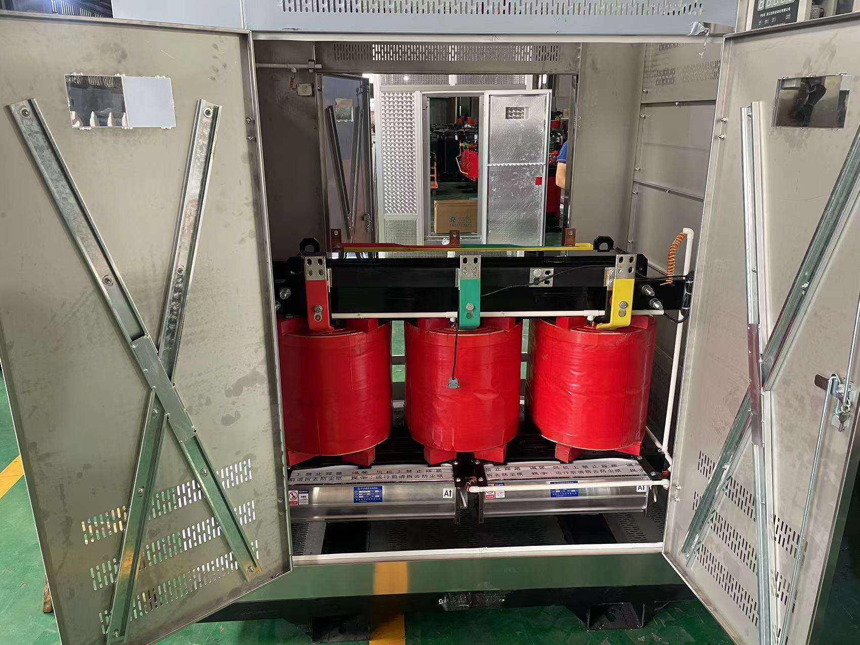
The gap between datasheet numbers and what happens after hours of sustained load often comes down to how heat is moved and where it is allowed to sit. Passive cooling looks clean on paper, but real enclosures trap pockets of warm air near critical components unless vent placement and internal baffles are treated as part of the design, not as afterthoughts. A well-chosen thermal pad or gap filler can lower junction temperatures more than a larger fan in the wrong spot.
Insulation is rarely just about keeping heat in or out. In humid conditions, the wrong surface temperature invites condensation, which becomes a slow-moving reliability problem for anything carrying current. Closed-cell foams and aerogel blankets behave very differently once dust, vibration, and repeated thermal cycling enter the picture. The best choices tend to be the ones that stay predictable after the first six months, not just during initial testing.
Real-world performance also depends on how cooling and insulation interact with the surrounding environment. A tightly sealed system may need a pressure equalization path so that cooling cycles do not pull moisture through gaskets. Similarly, adding more insulation around one area can shift the dew point somewhere worse. The practical goal is usually balance: enough thermal resistance to protect sensitive parts, enough air movement to avoid heat soak, and materials that will not degrade quietly over time.
Fire-Safe Design Details Most Specification Sheets Overlook
Spec sheets tend to treat firestopping as an afterthought, burying it in a single line that says little more than “seal all penetrations.” The real failures usually happen at the awkward intersections: a rated wall meeting a fluted deck, a plumbing stack shifting direction inside a concealed chase, or a conduit rack punching through a shaft wall in a tight corner. By the time someone notices the gap, the assembly rating no longer exists on paper or in the field. Good fire-safe design means drawing these transitions explicitly, not leaving them to the installer’s best guess.
One detail that rarely gets enough attention is the deflection joint at the top of a fire-rated wall. Specifications often call out stud spacing and board layering but stay silent on how the assembly should track movement under live load, wind sway, or thermal expansion while still holding back smoke and flame. If the joint filler cracks or pulls away after the first year, the wall is no longer doing its job. The same problem appears at slab edges and curtain wall bypasses, where membrane continuity depends on product compatibility and tested movement capacity rather than a generic caulk note.
Another frequently overlooked condition is what happens behind finishes. Recessed electrical boxes, data outlets, and small plumbing penetrations get sealed with whatever firestop material happens to be on the truck, regardless of whether it matches the listed assembly. Once one wall is compromised, building pressure differences can pull smoke through paths that never appear in a standard detail library. Design documents should specify not just the product, but how it must be installed, inspected, and documented before concealment, because the concealed failures are the ones no one discovers until it is too late.
Smart Sensors and the Shift from Reactive to Predictive Upkeep
For decades, maintenance teams operated on a simple but costly logic: fix it when it breaks. The reactive model meant equipment ran until failure, and every breakdown brought unplanned downtime, rushed spare parts orders, and a ripple of delayed production. Smart sensors have quietly dismantled that logic. By continuously measuring vibration, temperature, pressure, and current draw, these small devices turn a machine's own operating data into an early warning system. A slight rise in bearing temperature or a new frequency spike in a motor's vibration signature no longer goes unnoticed until the bearing seizes. Instead, it becomes a signal that maintenance can be scheduled for next Tuesday, not next quarter's emergency.
The real shift isn't just about seeing more data; it's about changing who makes the decision and when. In the old reactive world, a technician would arrive after a failure and try to reconstruct what happened. In a predictive setup, the sensor data feeds into models that recognize normal operating envelopes for each asset. When a pattern drifts outside that envelope, the system flags it with enough lead time for a planned intervention. This doesn't replace the technician's judgment—it gives them better evidence. A maintenance manager can choose to swap a pump's impeller during a routine batch changeover instead of at 2 a.m. on a Sunday when the line suddenly stops.
What often gets overlooked is how this shift rewires daily habits. Teams stop dreading phone calls about broken equipment and start checking condition trends over morning coffee. The conversation moves from "what went wrong?" to "what's changing, and how fast?" Plants that make this transition tend to carry less spare inventory because they no longer stock parts for every possible sudden failure. They also build a deeper familiarity with their machines—not from repairing them after the fact, but from watching how they behave under different loads and seasons. Smart sensors don't eliminate all surprises, but they turn the rare unexpected failure from a routine crisis into a genuine anomaly worth investigating.
Where Automatic Dry Type Transformers Fit in Modern Power Networks
They show up where fire risk and maintenance access push liquid-filled units out of the question. High-rise commercial towers, hospitals, underground rail stations, university campuses, and water treatment plants often install them close to occupied spaces or in sublevel vaults where oil containment would be expensive and unpopular. In these settings, automatic dry-type transformers earn their place less through headline efficiency and more through practical fit: no oil containment, reduced clearance requirements, and built-in monitoring that flags insulation stress before it becomes a failure.
Their role grows in networks with distributed generation and storage. A unit tied into a building management system can adjust voltage or signal winding temperature long before an operator walks the room. Solar plants, battery energy storage systems, and small industrial microgrids use them at the edge of the grid, where compact, air-cooled construction and automatic monitoring simplify approvals and reduce routine inspection.
On the network side, automatic dry-type transformers fit well in secondary distribution and retrofit projects where space and outage windows are tight. Because they can be installed closer to load centers without fire-rated vaults, utilities and facility engineers can shorten low-voltage cable runs, reduce voltage drop, and avoid the cost of remote oil containment. The automatic part often matters most during overload or thermal cycling: built-in controllers can log hot-spot data, trip cooling fans, or send alarms through standard building protocols, giving operators a clearer picture of an asset that otherwise runs quietly in a corner.
Matching Voltage, Load, and Environmental Demands Without Guesswork
Treating voltage, load, and environment as separate checks is what turns a straightforward match into a series of late-stage surprises. A 24 V rail that looks stable on a bench supply can swing wide when a motor drive brakes or a relay bank opens. The workable approach is to draw one envelope that includes supply tolerance, line regulation, load-step recovery, and the actual voltage limits of every device on that rail. When the envelope overlaps in all corners, the match holds without anyone having to see what happens.
Load behavior rarely sits still long enough for a single number to be useful. Inrush, capacitive charging, periodic pulses, and low-duty-cycle bursts pull current in ways that average readings hide. Capturing a real current waveform over the worst-case startup and shutdown sequence gives you the shape of the demand. From there, voltage margins can be set with actual data in hand, including derating for hot spots and minimum operating levels at the lowest expected input.
Environmental conditions change the physical rules quietly. Humidity, condensation, altitude, dust, and salt exposure alter creepage distances, cooling paths, and component drift. Instead of treating these as final qualification hurdles, make them early design inputs with numeric limits. A component that meets its electrical spec at room temperature can drift or degrade under thermal cycling, so build the envelope around the full operating range and keep field measurements feeding back into the next revision.
FAQ
They remove liquid insulation entirely, which lowers fire risk and eliminates the need for oil containment pits. That allows them to be installed closer to occupied areas without the heavy civil work often required for liquid-filled designs.
Advanced core materials and winding layouts keep losses low at partial load. Automatic controls can adjust voltage regulation or cooling fans as demand shifts, so the unit does not waste energy during lighter operating periods.
Yes. The solid insulation and enclosed construction help limit arc spread, resist moisture ingress, and avoid leaks that could contaminate surrounding spaces. This makes them suitable for hospitals, data centers, tunnels, and crowded industrial rooms.
Sensors typically measure winding and core temperature, load current, voltage, and sometimes humidity or partial discharge. The information flows to a local controller or building management platform, giving operators a live view of equipment health.
It can, because maintenance shifts from fixed intervals to condition-based action. Early detection of thermal stress, repeated overloads, or cooling problems helps prevent insulation aging and keeps the transformer within safe limits longer.
In indoor or environmentally sensitive locations where fire safety, clean operation, and simple containment are important. Typical sites include commercial high-rises, university buildings, production lines, and renewable energy installations near occupied areas.
Even with smart monitoring, regular visual checks, ventilation cleaning, connection torque verification, and sensor calibration remain important. The system identifies when intervention is needed, but it does not replace hands-on maintenance entirely.
Automatic voltage regulation and cooling control reduce manual switching. The transformer responds to changing conditions on its own, protecting downstream equipment from voltage drift and simplifying remote or unattended operation.
Conclusion
Automatic dry type transformers earn their place in modern networks less through catalog efficiency figures and more through how they handle the conditions those figures never capture. Load profiles shift constantly, harmonics push thermal limits, and ambient conditions rarely match test-bench assumptions. The real efficiency edge shows up when cooling paths, insulation class, and voltage matching are selected around actual duty cycles rather than a single kVA rating. That means weighing enclosure ventilation, winding temperature rise, and short-circuit withstand together, not as isolated line items.
Safety and monitoring are where the design becomes an operational asset instead of a passive component. Fire-safe construction removes the liquid-filled failure modes that facility planners often assume are unavoidable, while embedded sensors turn temperature, partial discharge, and cooling performance into trending data. Maintenance shifts from scheduled guesswork to targeted intervention, reducing downtime without inflating budgets. In commercial buildings, industrial plants, and renewable hubs alike, the value lies in matching voltage, load, and environment carefully, then letting continuous monitoring protect that decision over time.
Contact Us
Contact Person: Kellen Chen
Email: [email protected]
Tel/WhatsApp: 8613806536768
Website: https://www.cnxiaopai.com