

China Flange Penstock Gate Design Considerations for Reliable Hydropower Infrastructure
2026-08-17
Hydropower projects demand components that can withstand immense pressure and deliver fail-safe performance over decades. Among these, the flange penstock gate plays a pivotal role—yet its design is often underestimated. From material selection to sealing mechanisms, every decision impacts the long-term reliability of the entire infrastructure. In China, where large-scale hydropower continues to expand rapidly, engineers are refining these gates to meet increasingly stringent operational demands. What separates a dependable gate from a potential point of failure? The answer lies in a set of design considerations that go beyond standard specifications—and THT has been at the forefront of applying them.
Matching Flange Ratings to Penstock Pressure Cycles
Penstock systems rarely hold a steady pressure; they breathe with turbine starts, load rejections, and emergency shutdowns. A flange class chosen solely on the highest static head can pass a hydrotest yet still develop weepy joints after a few hundred cycles. The real yardstick is the pressure envelope—how often the line swings from near-zero to peak and how sharply those reversals occur. Matching a flange rating here means looking beyond the ASME B16.5 pressure-temperature table and checking the cyclic amplitude against the fatigue endurance of the bolted assembly.
One practical approach is to plot the expected pressure cycles on the same axis as the flange's allowable stress range. If the cycling stays within the lower third of the rating's cold working pressure, standard raised-face flanges with spiral-wound gaskets often suffice. When transients push the envelope repeatedly into the upper quartile, a heavier class or a different sealing concept—such as a ring-type joint—becomes cheaper than chasing nuisance leaks during every maintenance window. The bolt preload also matters more than the flange class itself; insufficient tension lets the joint breathe with each cycle, while controlled tightening keeps the gasket seated through reversals.
Field records from hydro plants show that most flange-related failures are not sudden bursts but slow degradation of the gasket contact stress. That points to a rating strategy based on cumulative fatigue rather than a single worst-case spike. A Class 300 flange may look oversized on paper for a 40-bar penstock, but if the daily pressure cycle includes a 15-bar swing, the extra stiffness pays for itself in longer gasket life and fewer retorques. The goal is to match the flange's cyclic pressure capacity to the penstock's actual operating rhythm, not to the static design head alone.
Why Chinese Hydropower Sites Demand Tougher Gate Materials
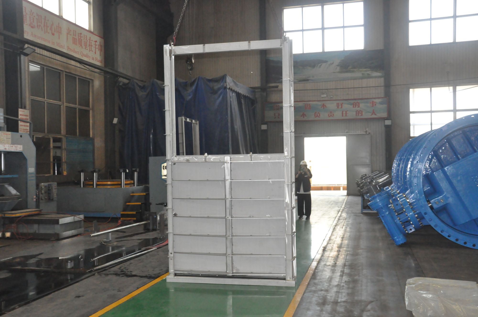
China's southwestern hydropower corridors sit inside steep, narrow valleys where rivers carry exceptional sediment loads, especially during the flood season. Gates in these plants are not just static barriers—they cycle open and shut to manage water levels and discharge, and each movement drags silt, sand, and gravel across the bottom seals and side guides. Ordinary carbon steel panels often show measurable thinning and seal failure after only a couple of flood seasons, forcing unplanned outages and costly dry-dock repairs. To stretch maintenance intervals and avoid sudden operational risks, plant owners now specify gate materials with much higher surface hardness and abrasion resistance, such as stainless-clad plates or duplex steels that can shrug off the constant scouring.
There is also the combined effect of high head and cavitation. Many new stations operate with heads exceeding 200 meters, and when gates are partially open, powerful vortices and low-pressure zones form downstream. Vapor bubbles collapse against the metal surface with enough force to pit ordinary steel within months, creating pinholes that quickly grow into structural weak points. On top of that, frequent seismic activity and large temperature swings demand a material that keeps its toughness and weldability after years of cyclic loading. As a result, design specifications have gradually raised the bar for impact energy, tensile strength, and pitting resistance, pushing suppliers toward more refined alloys, controlled rolling processes, and post-weld treatments that were rarely considered for older plants.
Silt and Debris: Designing Seals That Keep Working
Real-world sealing problems rarely start with clean fluid. Silt, sand, and fine debris embed themselves in seal lips, abrade shaft surfaces, and pack into cavities until the elastomer can no longer follow the mating surface. A seal that survives a clean bench test can fail within days on a muddy construction site or in a river dredge pump. The first line of defense is often material choice: high-acrylonitrile NBR or hydrogenated nitrile resists cut growth better than standard nitrile, while polyurethane offers excellent abrasion resistance but needs careful attention to hydrolysis in wet environments.
Geometry matters just as much. A steep, well-supported lip angle can scrape debris away from the sealing interface instead of letting it wedge underneath. Adding a secondary dust lip or an excluder lip creates a labyrinth path that keeps larger particles out of the primary sealing zone. In heavily contaminated applications, positive-pressure grease or clean fluid flushing between the lips provides an active barrier, pushing back against the ingress of fine silt. Some designs even use a V-ring or a radial exclusion device mounted on the shaft to throw off debris by centrifugal force before it reaches the main seal.
The installation environment is the final piece. If dirt falls onto the shaft during assembly or maintenance, no seal design can compensate. Using seal installation tools that protect the lip from nicks, wiping down shafts before fitting, and orienting drain ports so debris can escape rather than accumulate all extend real service life. Testing should include cycling in a slurry or dust chamber rather than relying only on clean-oil benchmarks. Seals that keep working in silt and debris are not just a better part—they are the result of decisions made at the material, geometry, and service level together.
Thermal and Hydraulic Stress Patterns in Long Penstocks
Long penstocks carry water under high pressure across steep terrain, and their steel or concrete walls face two constantly shifting forces: thermal expansion from daily temperature swings and hydraulic pressure from flow changes. At dawn, the pipe surface cools quickly while the water inside retains heat from the previous afternoon, creating a gradient that pulls the steel inward. As the day warms, the outer wall expands faster than the inner layer, and the resulting bending stress concentrates near anchor blocks and expansion joints. These daily cycles rarely cause immediate failure, but over decades they initiate micro-cracks that grow with each temperature reversal.
Hydraulic stress operates differently, spiking during emergency shutdowns or rapid valve closures. A sudden stop sends a pressure wave upstream, briefly adding several hundred kilopascals to the static head. In a long penstock, this wave reflects off bends and bifurcations, creating temporary zones where tensile stress rivals the yield point of older mild steel. Operators often reduce risk by programming slow closure times, but unplanned trips—from turbine bearing failure or grid loss—still produce the sharpest spikes. Field strain gauges on a 2.4-kilometer penstock in the Andes recorded peak dynamic stress at 62% of yield strength during a single fast-acting valve test, a margin thin enough to worry inspectors.
The interaction between thermal and hydraulic loads is rarely linear. A cold morning pipe already carries residual tensile stress from night contraction; when a flow surge hits that same section, the combined stress can exceed what either effect would cause alone. Maintenance teams often schedule pressure tests in the late afternoon when thermal gradients are smallest, avoiding false alarms from temperature-induced expansion. Modern monitoring systems combine fiber-optic strain sensors with thermal inertia models to separate the two signatures, letting engineers predict which support piers will see the most fatigue over the next twenty years.
Corrosion Pitfalls in Dam Environments and How to Avoid Them
Dams face corrosion threats that rarely announce themselves until structural steel has already lost significant cross-section. Water chemistry shifts with seasons and stratification, so dissolved oxygen, chloride, and sulfate levels can vary sharply between the surface and deep outlets. Stagnant pockets behind spillway gates or inside intake towers set up oxygen concentration cells, driving pitting at welds, crevices, and coating holidays. Add in sulfate-reducing bacteria that thrive in low-oxygen silt and produce hydrogen sulfide, and you get accelerated attack even where oxygen levels seem too low to matter. These pitfalls are seldom uniform—they concentrate where protective coatings were poorly applied, where debris accumulates, or where dissimilar metals meet.
Avoiding these failures begins with matching materials and coating systems to the actual water chemistry, not a generic spec. Fusion-bonded epoxy and moisture-cured polyurethane can hold up well, but only if mill scale, rust, and soluble salts are removed before application. For submerged steel, cathodic protection—whether sacrificial anodes or impressed current—needs careful current distribution modeling; too little protection leaves pits active, while too much can cause hydrogen embrittlement or coating disbondment. Underwater inspections with divers or ROVs should target known weak spots: gate guides, seal plates, bolted flanges, and the transition zone where water level fluctuates daily.
Operational habits matter as much as design. Long periods of low flow let stagnant, oxygen-depleted water sit against metal surfaces, encouraging microbial corrosion and concentration cells. When dewatering for maintenance, blast clean and recoat exposed steel thoroughly, paying extra attention to threaded connections and drain holes where moisture lingers after refilling. Tracking water quality trends over multiple seasons reveals when corrosive conditions peak—often during turnover or after heavy runoff—so maintenance windows can be planned around actual risk rather than fixed calendar intervals.
Field-Adjustable Gate Mounts for Faster Maintenance
Most gate hardware assumes perfect alignment from the day it leaves the factory, but real-world installation rarely cooperates. Our field-adjustable mounts let crews dial in vertical and lateral positioning on site without cutting, shimming, or re-welding. A quick twist of the eccentric collar shifts the gate leaf by up to 3/8 inch in any direction, so sagging posts or uneven concrete no longer force a teardown. That means fewer callbacks and a cleaner finish on day one.
Routine maintenance often grinds to a halt when a gate starts dragging or latching poorly. With standard fixed mounts, you would unbolt the panel, add washers, and hope for the best. These adjustable mounts change the math: a single service tech can loosen two set screws, nudge the gate back into plumb, and retighten in under five minutes. Because the adjustment mechanism is fully contained, there are no loose parts to drop or lose in the grass. The result is a repair process that feels less like surgery and more like tuning an instrument.
Durability does not take a back seat to convenience. The sliding wedges are machined from stainless steel and coated with a dry-film lubricant, so repeated adjustments won't gall or seize, even in coastal or high-humidity environments. After installation, the set screws recess below the housing face, leaving nothing to snag clothing or catch on livestock trailers. For facilities managing dozens of gates, that small design detail translates into noticeably shorter maintenance windows and a lot less frustration for the crew on the ground.
FAQ
Flanged joints allow for precise alignment and secure fastening under the massive pressure heads typical of penstocks. They also permit controlled disassembly for inspection or seal replacement without cutting into the pipe wall, which is a major advantage during long service intervals.
Choosing a gate body and flange material with matching thermal expansion coefficients reduces stress at bolted interfaces. High-strength carbon steel or duplex stainless steel is often preferred because it resists both mechanical fatigue and pitting, while ensuring the flange faces remain dimensionally stable after years of load cycling.
Using pre-compressed gaskets with controlled bolt torque, plus machined flange faces with tight flatness tolerances, creates a reliable seal. Adding secondary containment rings or monitoring ports can provide early warning if the primary seal begins to degrade, avoiding unplanned shutdowns.
Gate closure generates unbalanced thrust and bending moments that transfer through the flange bolts. Detailed finite element modeling of the gate, flange, and adjacent pipe segments helps identify peak stress zones, allowing designers to reinforce bolt circles or add stiffening ribs where fatigue cracks are most likely to initiate.
Coatings and cathodic protection systems prevent corrosion that can jam gate guides or erode flange sealing surfaces. A well-selected epoxy or thermally sprayed aluminum layer not only extends the structure's life but also keeps emergency gate operation smooth, which is critical for dam safety.
Arranging flanges so that gate sections can be unbolted and lifted vertically without removing adjacent piping saves time during overhauls. At the same time, using heavy-duty bolting patterns and reinforced flange necks preserves the stiffness needed to handle water hammer loads, ensuring that accessibility does not compromise strength.
Bolt loosening from vibration, gasket creep under sustained pressure, and fatigue cracking at weld toes near flanges are common issues. Specifying wedge-locking washers, selecting gaskets with high recovery properties, and using full-penetration welds with post-weld heat treatment can significantly lower the likelihood of these failures.
In mountainous regions with large temperature swings, expansion joints and flexible flange couplings are sometimes introduced to absorb thermal movement. For projects like those along the Jinsha River, designers often use thicker flange plates and additional bolt holes to handle high sediment loads and rapid pressure fluctuations, tailoring each design to local hydrology and geology.
Conclusion
Hydropower stations across China's mountainous river basins present a demanding combination of pressure fluctuations, abrasive silt, and wide temperature swings. Flange connections on penstock gates cannot be selected solely on nominal pressure; they must be matched to the full spectrum of transient pressure cycles that occur during load rejection and emergency shutdown. At the same time, gate bodies and sealing faces need tougher alloys or hardened overlays, because sediment-laden flow wears down ordinary carbon steel quickly. Seal design often dictates long-term reliability: a robust seal must shed fine silt and debris rather than trap it, and it should tolerate repeated flexing from thermal expansion of long penstocks.
Field experience also points to corrosion and maintenance as decisive factors. Dam environments combine high humidity, stray currents, and aggressive water chemistry, so protective coatings and cathodic protection have to be planned from the start rather than retrofitted. Thermal gradients along a kilometer-long penstock and water hammer stresses can shift gate alignment over time, which is why adjustable gate mounts and replaceable wear strips make a practical difference. By integrating pressure-rated flanges, silt-resistant seals, corrosion control, and field-adjustable mounting, designers can deliver penstock gates that remain reliable under China's harsh operating conditions without excessive downtime.
Contact Us
Contact Person: Su Zhang
Email: [email protected]
Tel/WhatsApp: +86-25219206
Website: https://www.tht-valve.com/