

OEM PTFE Gland Packing: Essential Guide for Industrial Sealing Solutions
2026-11-01
Sealing failures in industrial settings are rarely sudden—they're usually the result of a packing that wasn't quite right for the job. When temperatures spike, chemicals attack, or shafts start to wear, the wrong gland packing gives out long before it should. OEM PTFE gland packing flips that script. It's not another generic filler; it's a precision-engineered barrier built for the harshest rotary and reciprocating services. Whether you're fighting leaks in a chemical pump or chasing longer maintenance intervals in a mixer, the material and construction details make all the difference. And that's where TAIFNO enters the picture—not as just another supplier, but as a manufacturer that treats PTFE packing as a science, not a commodity. In this guide, we'll break down what actually matters when selecting OEM PTFE gland packing, from filler choices to break-in behavior, so you can stop replacing seals and start solving them.
Why PTFE Gland Packing Holds Up Where Other Materials Wash Out
In pump shafts and valve stems exposed to aggressive chemicals or abrasive slurries, traditional packing materials often degrade within weeks. Graphite crumbles under high shaft speeds, aramid fibers swell and lose dimensional stability, and flax-based options simply dissolve. PTFE gland packing survives these conditions because its molecular structure is nearly inert. It doesn't react with acids, solvents, or oxidizing agents, so the packing retains its cross-section and sealing force long after other materials have turned into mush.
The real differentiator is how PTFE handles friction and heat. Most packings rely on external lubricants that wash out under constant flow, leaving dry fibers to scorch and score the shaft. PTFE, by contrast, has one of the lowest coefficients of friction of any solid, and it transfers a thin film onto the mating surface during break-in. That self-lubricating layer means the packing doesn't need a continuous lubricant supply to stay cool. Even when process fluids momentarily interrupt, the shaft won't gall or overheat, which is exactly where graphite-based packings tend to fail catastrophically.
Another overlooked advantage is cold flow under load. While that property is often cited as a weakness in structural applications, in gland packing it works in your favor. As the gland follower compresses the PTFE rings, the material deforms slightly to fill microscopic imperfections in the stuffing box and shaft. This creates a tighter, more uniform seal without requiring excessive gland pressure. So instead of fighting the packing to stop leaks, you get a conformable barrier that adapts to wear and vibration—keeping process fluid in and contaminants out far longer than stiffer, more brittle alternatives.
Cross-Section Selection: The Step Most Maintenance Teams Skip
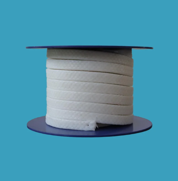
In the rush to get equipment back online, a lot of maintenance crews jump straight to sourcing a replacement part without ever questioning the original cross-section. That's where failures quietly start. A shaft that's been wearing prematurely isn't always about the material—it's often the shape. A round bar might look fine on paper, but if the load path isn't axial, a hollow tube or a profiled section like an I-beam or T-section would shed weight and handle bending far better. Yet most teams skip this analysis because it feels like an engineering luxury, not an urgent fix. The result is a cycle: replace, run, fail, repeat.
Skipping cross-section selection also shows up in fasteners, framing members, and even conveyor rollers. A solid square bar might be swapped in for a broken C-channel because it's what the storeroom has. But the original channel wasn't arbitrary—its open side allowed for drainage, reduced thermal expansion stress, or made room for an adjacent guard. When maintenance ignores those geometric details, the new part can create interference, trap moisture, or concentrate stress at the mounting holes. It's not just about strength; it's about how the shape interacts with the whole assembly under real conditions.
The fix doesn't require a full design review. A quick sketch, a photo of the failed part, and ten minutes comparing a few standard profiles against the actual load direction can break the cycle. Some plants now keep a small chart near the parts cage showing common cross-sections alongside their bending and torsional stiffness ratings. It's a low-cost habit that forces the team to ask: was this shape chosen for a reason, or just because it was easy to make? Often the difference between a chronic failure and a stable machine is exactly that question.
Custom OEM Packing Profiles for Oddball Stuffing Boxes
When a standard packing ring won't seat properly in an off-spec stuffing box, the usual fix is to either machine the box or settle for excessive leakage. Neither is ideal. Custom OEM packing profiles solve this by matching the exact gland depth, bore ID, and stem OD of the oddball assembly—including wear-induced ovality or stepped bores that aren't on any manufacturer's drawing. The cross-section doesn't have to be square; we've produced trapezoidal, L-shaped, beveled, and even multi-lip profiles that drop right into legacy valves, mixers, and reciprocating pumps where off-the-shelf packing simply binds or blows out.
What separates a true custom profile from a resized standard ring is the development process. It starts with a dimensional survey or a used set of packing rings as a reference, then moves to a profile extrusion or compression molding die built specifically for that geometry. Material choice follows the service: flexible graphite with Inconel wire reinforcement for high-temperature steam, aramid fiber with PTFE dispersion for abrasive slurries, or food-grade expanded PTFE for sanitary oddballs. Because the profile is cut and skived to the exact stuffing box depth, installation takes minutes instead of hours—and the gland follower finally lands where it was designed to.
For OEMs and maintenance crews dealing with orphaned equipment, custom packing profiles are often cheaper than re-engineering the stuffing box. We keep the die on file, so reorders match the original geometry without another field measurement. That reproducibility matters when a plant runs twenty identical "non-standard" pumps that were modified in the 1980s and have no surviving documentation. Instead of reverse-engineering every outage, the packing becomes a controlled part number—same profile, same compression, same leak-off performance.
Cutting and Installing PTFE Rings Without Creating Leak Paths
Cutting PTFE rings demands more care than most machinists expect. A dull blade or a hurried scoring pass can leave micro-tears along the edge that later open under pressure. Use a fresh, fine-tooth blade or a dedicated PTFE cutting jig, and make one continuous, controlled motion rather than sawing back and forth. Deburr the cut ends with a soft brass scraper—never sandpaper, which can embed grit into the surface and create a path for fluid to follow.
Installation is where leak paths commonly appear, especially if the ring gets twisted or overstretched. Warm the ring slightly with a heat gun on low, just enough to restore flexibility, then slide it over the shaft using a smooth plastic sleeve or a wrapping of PTFE tape as a guide. Avoid using sharp picks or screwdrivers to lever the ring into the groove; any nick or scratch on the sealing face becomes a direct route for leakage once the system reaches operating pressure.
After seating the ring, run a fingertip along the entire circumference to feel for bumps, flat spots, or uneven compression. If the ring ends do not meet cleanly—either overlapping or leaving a visible gap—remove it and recut rather than forcing it into position. A correctly installed PTFE ring should sit flush and uniform in the groove, with no shiny drag marks or whitened stress zones, because those are exactly where a leak path will eventually form.
How Temperature, Pressure, and Speed Team Up Against Your Packing
Most operators treat temperature, pressure, and speed as separate dials, but on a packaging line they gang up quickly. A small drop in sealing temperature combined with a pressure spike can tear film or leave weak seals, while speed changes amplify both. The result is rarely a single obvious fault; it is a mix of wrinkles, partial seals, and material waste that shifts from shift to shift.
For example, raising line speed usually shortens dwell time, so the same heat and pressure that sealed perfectly at lower speeds now produce cold seals or wrinkles. If you compensate by cranking up temperature, you risk melting through thin films, especially when pressure rollers are already set too high. The interaction is non-linear, and chasing one variable while ignoring the others tends to make defects move rather than disappear.
To keep them from teaming up against you, map the safe operating window for your material. Run small step changes on one variable while holding the other two fixed, then record where failures appear. You will often find that moderate settings across all three outperform aggressive optimization of any single factor, and that stability matters more than hitting an ideal number.
Early Warning Signs of Packing Failure Hidden in the Wear Pattern
A ring of fine, powdery debris accumulating near the stuffing box often passes for routine leakage, but its texture tells a sharper story. When the packing sheds material in thin, talc-like layers rather than forming occasional droplets, the friction cycle has already shifted. This kind of wear suggests the packing is being ground down by a shaft with micro-imperfections, or that lubrication has been squeezed out of the fiber structure. Instead of adding more gland pressure, inspect the runout and surface finish first; chasing the leak by tightening usually accelerates the breakdown.
Look at the pattern left on the rings after removal. Uniform darkening across the inner bore is normal, but a series of glassy, polished stripes points to localized overheating. Those stripes form where individual packing rings slide against the shaft without rotating, often because the gland follower is cocked or the stuffing box depth doesn't match the ring count. Another overlooked clue is a wedge-shaped wear profile: thicker at the bottom, thinner at the top. That asymmetry indicates the shaft is running off-center under load, so the packing is doing the job of a bearing, not a seal.
Pay attention to where the wear stops. A sharp, shiny band at the throat of the stuffing box, with untouched material deeper inside, reveals that most of the sealing action is happening on a single ring. The others are simply riding along, adding friction without sharing the load. This pattern often precedes sudden leakage because the working ring has already lost its resilience. Replacing only that ring rarely fixes the root cause; the misalignment, pressure imbalance, or incorrect packing cross-section remains. Read the wear like a service record: it records every misstep before the failure announces itself.
FAQ
PTFE’s low friction and near-universal chemical resistance let it handle aggressive media without breaking down or scoring shafts. The material also runs cooler than many alternatives, which translates to longer packing life and less frequent adjustments.
Custom packing makes sense when equipment has non-standard stuffing box dimensions or unusual operating conditions. An OEM can tailor the cross-section, density, and impregnation to match specific pressure, speed, and chemical exposure, avoiding the compromises of off-the-shelf products.
PTFE has very low friction, so it generates less heat than graphite or aramid packings. That matters at higher shaft speeds where heat buildup can cook lubricants and cause premature failure. But you still need a proper break-in procedure and enough leakage to keep the packing lubricated.
Using too many rings, overtightening the gland follower, and cutting rings to the wrong length are the big ones. PTFE packing needs some leakage for cooling and lubrication, so cranking down to a zero-drip condition usually leads to burnt packing and scored shafts.
Standard PTFE packing is not the best choice for abrasive slurries because particles can embed in the packing and wear the shaft. For those applications, a filled PTFE or a hybrid design with a harder wearing surface often works better, but it depends on particle size and concentration.
Start with the gland loose, bring the equipment up to operating speed, then tighten gradually over a period of hours or days while monitoring leakage and temperature. The goal is to reach a steady leak rate of about 10–20 drops per minute for rotating shafts, without excessive heat.
Fillers modify the base PTFE to improve thermal conductivity, extrusion resistance, or wear characteristics. For example, graphite-filled PTFE dissipates heat better, while glass-filled PTFE adds strength for high-pressure services. The right filler depends on the specific sealing environment.
Conclusion
PTFE gland packing earns its place in harsh industrial service because it shrugs off aggressive chemicals, steam, and solvents that wash out graphite or aramid alternatives. Its low friction also protects pump shafts and valve stems from scoring. But material alone is not a full solution. The cross-section you choose matters more than many teams realize. A packing that does not match the stuffing box profile will extrude, overheat, or leave uneven compression paths. For standard boxes, square sections often work, yet many OEM applications involve oddball geometries, worn housings, or deep stuffing boxes that demand a custom profile. Working with an OEM partner to machine or braid a packing to the exact cross-section prevents blow-by and extends service life. If you skip this step, you will likely re-pack sooner than expected, regardless of how good the PTFE compound is.
Installation errors are another common failure point. Cutting PTFE rings straight across or using mismatched ring ends creates direct leak paths. Each ring should be cut on a diagonal, installed with joints staggered at least 90 degrees, and seated individually to avoid gaps. Once running, temperature, pressure, and shaft speed work together against the packing. High speed generates frictional heat, high pressure tries to extrude the material, and thermal cycling can cause hardening or shrinkage. Watch the removed packing for early warning signs. A hard, glazed surface suggests over-tightening or insufficient lubrication. Extruded edges mean the cross-section was too soft or clearances too large. Uneven wear on one side points to misalignment or a bent shaft. Reading these wear patterns lets you correct the real problem before a minor leak becomes an unplanned shutdown.
Contact Us
Contact Person: Tommy Xiao
Email: [email protected]
Tel/WhatsApp: 8615651509888
Website: https://www.ptfe-factory.com