

USB Type-C Cable Factory Checklist: What to Verify Before You Order
2026-10-13
Ordering USB Type-C cables in bulk seems straightforward—until a shipment shows up with loose connectors, flimsy shielding, or power delivery that falls short of spec. That’s exactly why a factory checklist matters before you commit. This guide walks through the non-negotiables: from connector fit and e-marker chips to cable length tolerances and USB-IF certification. If you’d rather skip the guesswork, EBCYX has already done the homework on reliable manufacturing partners.
USB-IF Certification Should Be Your First Filter
When you're sorting through USB-C cables, chargers, or docks, an overwhelming number of options promise the same specs. The quickest way to cut through the noise is to check whether the product actually carries USB-IF certification. This isn't a marketing badge; it means the manufacturer submitted the item for testing against a defined set of electrical, mechanical, and protocol requirements. Without that baseline, you're relying on a vendor's word, which often doesn't hold up under real-world charging or data transfer loads.
The reason this should be your first filter rather than an afterthought is simple: USB-C is deceptively complex. A cable that looks identical to another might use thinner power wires, skip required resistors, or misreport its capabilities to your phone or laptop. That can lead to slow charging, dropped connections, or, in worst-case scenarios, damage to your device's port or battery. Certified products remove that guesswork because they've been tested for interoperability across the USB ecosystem, not just in one lab setup.
It also saves you time. Instead of reading dozens of user reviews hunting for hidden failures, you can set the certification requirement up front and narrow your list to products that met a minimum bar. From there, you can compare price, length, or design knowing that basic safety and signal integrity are already covered. If a product lacks certification, you have to ask what else the maker cut corners on.
Pin Layout Tolerances Are Where Cheap Factories Slip
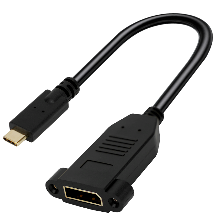
Pin layout tolerances in PCB assembly refer to the allowable deviation in the position and spacing of component pins relative to their designated pads. These numbers look trivial on paper, often just a few tenths of a millimeter, but they decide whether a board can survive automated soldering and long-term thermal cycling. Factories that chase the lowest cost tend to treat these tolerances as soft suggestions instead of hard limits. Their pick-and-place machines may not receive regular calibration, and the operators rarely recheck pin alignment after a batch changeover. The result is a slow drift that no one notices until the boards start failing electrical test.
The first visible symptom is usually a rise in solder bridging or head-in-pillow defects, where the pin touches the paste but never forms a proper intermetallic bond. Because each individual board still looks almost correct to the naked eye, quality inspectors may pass the lot. Over time, these marginal connections weaken under vibration or temperature swings, leading to field returns that cost far more than the initial savings. A cheap factory will often dismiss this as bad luck or blame the component supplier, rather than checking their own placement data against the datasheet tolerances.
To avoid getting caught, buyers should request tolerance verification reports from the pick-and-place process, not just final board dimensions. A trustworthy manufacturer will share the measured pin offsets for each batch and explain how they stay within the component's specified layout envelope. If a factory cannot produce these numbers or insists that pin layout tolerances are over-engineering, that is a clear warning sign. In electronics, the places where cheap factories slip are rarely dramatic; they hide in the fractions of a millimeter that separate a reliable product from a time bomb.
Shielding and Signal Integrity Need a Real Stress Test
Most shielding solutions look fine on paper. They meet the datasheet specs, pass the standard swept-frequency tests, and get stamped for compliance. But real-world signal integrity rarely follows a clean sine wave. Transient bursts, thermal cycling, mechanical flexing, and nearby high-power switching all pile stress onto shielding in ways a typical bench test never replicates. A shield that works at room temperature and low power can develop micro-cracks, lose contact integrity at seams, or shift resonance points once the board heats up and the chassis vibrates. Without pushing the assembly through those actual operating extremes, you are only verifying a theoretical model, not the product that ships.
Signal integrity is equally fragile under stress. Crosstalk, ground bounce, and impedance discontinuities often stay hidden until a PCB is driven hard with fast edges and dense simultaneous switching. A quiet lab bench with terminated test points will mask reflections that appear only when the return path gets shared, the reference plane flexes, or the connector plating degrades after repeated mating cycles. Stress testing means injecting realistic noise, running sustained data bursts, and monitoring eye diagrams while cranking up temperature and vibration together, not one at a time. That combination is what exposes marginal shielding gaskets, loose board screws, and resonances that only show up when the enclosure is fully assembled and hot.
A proper stress test should also include failure-mode exploration, not just pass/fail thresholds. Push the shield until it starts leaking, then document how much margin remains before bit errors appear. Cycle the temperature rapidly to create differential expansion between metal enclosure and PCB, then watch for intermittent ground loops. Only by deliberately breaking the system in controlled ways can you learn where the real design weaknesses are and fix them before field returns pile up. That is the difference between a shield that survives a spec sheet and one that survives the real world.
Mating Cycle Ratings Predict Field Failures Better Than Any Spec Sheet
Connector datasheets bury the mating cycle number in a corner, yet field returns tell a sharper story. A part rated for 500 cycles might survive 2,000 gentle bench insertions, but installers on a cold rooftop twist, yank, and force alignment under time pressure. Once the plating wears through or a latch loses its snap, intermittent opens begin long before the spec sheet admits defeat.
Real failures cluster around mechanical fatigue, not electrical overstress. Repeated plugging shaves microns off contact surfaces, loosens retention dimples, and cracks solder joints at the housing interface. Engineers who track warranty data quickly learn that a connector with a 10,000-cycle rating often outlasts one claiming a fancy impedance tolerance but only 250 cycles, simply because the field is a vibration-rich, thermally cycling, human-error environment.
The practical takeaway: treat the mating cycle rating as the primary reliability filter. If a vendor refuses to publish it or hides it behind vague wording, assume the worst. Testing a handful of samples through repeated connect and disconnect under angled load and temperature swings reveals more about long-term performance than any carefully curated electrical parameter table.
E-Marker Chips and Power Delivery Claims Are Easy to Fake
USB-C cables that promise 100 W or 240 W charging often rely on a tiny e-marker chip to tell the charger what the cable can handle. Those chips cost pennies and their data can be rewritten or cloned with cheap tools. A cable sold as high-power might carry an e-marker that reports 5 A and 20 V, while the actual copper wires inside are far too thin for that load. There is no visible way to spot the mismatch before you plug it in.
Because e-marker validation is rarely enforced at the factory, vendors can flash whatever numbers they want and print a familiar certification mark on the package. Even supposedly branded cables sometimes end up with recycled or counterfeit chips that don't match the physical hardware. The result isn't just slower charging; sustained overcurrent through undersized wires can melt connectors, damage ports, or trip protection circuits in unpredictable ways.
Independent testers keep finding cables where the e-marker data overstates capabilities by 200% or more. Without a USB PD analyzer or a load tester, most people can't detect a fake claim until something gets hot or stops working. That's why it's worth treating bold power-delivery numbers on budget cables as a starting point, not a guarantee, and confirming real-world performance before pushing a cable anywhere near its advertised limit.
Get the Factory's In-House QC Checklist in Writing
Never settle for a verbal promise that the factory “does quality control.” Ask for their actual in-house QC checklist in writing before production starts. This document should show exactly what they inspect, at which stages, and how often. If it arrives as a single page with vague phrases like “check appearance” or “ensure quality,” treat that as a warning sign. A real checklist includes specific measurements, defect tolerances, and the names or roles of people responsible for each checkpoint.
Look for details that make the checklist usable rather than decorative. Does it mention incoming material inspection, inline checks during assembly, and final pre-shipment review? Are there pass/fail limits for things like scratches, color variation, or dimensional accuracy? Ask for the current version with a date and revision number. If the factory cannot produce a dated, version-controlled document, their QC process is probably informal or inconsistent.
Once you have the checklist, compare it against your own quality requirements and flag any gaps. Keep a copy on file and use it as a reference during factory visits or third-party inspections. Have the factory walk you through the checklist on the production floor, showing where each check happens. If defects show up later, you can go back to the documented checklist and identify exactly which step failed or was skipped.
FAQ
Ask for their USB-IF TID (Test ID) for the specific cable model you're sourcing. A legitimate factory should provide the certification number and the associated compliance test report from an authorized lab. Cross-check the TID on the USB-IF public database. If they hesitate or offer only a "self-declaration," treat that as a red flag.
Insist on seeing test data for characteristic impedance (typically 90 ohms ±15% for USB 3.x), insertion loss, return loss, and crosstalk across the full operating frequency range. Also request E-Marker chip verification for cables rated above 3A or supporting USB4/Thunderbolt. If the factory cannot produce these from a recent production run, not just a golden sample, move on.
Check the conductor gauge and material—many cheap cables use copper-clad aluminum or steel, which causes voltage drop and heating. For USB Type-C with 5A current support, you want tinned copper conductors of at least 22 AWG for power lines. Also verify the braid and foil shielding coverage; ask for a cross-section cut or detailed BOM.
Request their incoming inspection process for the Type-C connector pins, especially the plating thickness on the contacts. A good factory will test for pin wear after insertion cycles (typically 10,000 cycles for USB Type-C). Ask for microscopic images of the connector tongue and a test report showing no bent or recessed pins after durability testing.
Watch for inconsistent pin alignment, loose connector fit, or cables that only work when inserted one way. Some factories use non-compliant resistors on the CC pins to fake fast-charging support. Also check if the cable gets warm during a 5A load test—excessive heat means poor conductor or contact resistance. If the sample fails any of these, the production run will likely be worse.
Yes, at least a virtual or third-party audit. Focus on their production line for cable assembly, especially soldering or crimping of the Type-C connector. Check whether they have automated optical inspection (AOI) for pin alignment and tensile strength testing equipment. Ask about their defect rate history and how they handle non-conforming batches.
You need the full compliance package: USB-IF certification, RoHS/REACH declarations, and if shipping to EU, CE marking under the Low Voltage Directive. Also ask for a detailed specification sheet that includes pinout, wire gauge, shielding type, and E-mark IC vendor. A factory that can't produce a coherent spec sheet likely doesn't control its supply chain well.
Ask for realistic monthly output for your specific cable configuration, not just "we can do it." Request a production schedule plan showing line allocation and testing throughput. A factory that quotes a suspiciously short lead time may cut corners on testing or use pre-assembled subpar components. Check if they can provide past order references with consistent quality.
Conclusion
Before placing any USB Type-C cable order, push past glossy spec sheets and demand proof that the factory holds USB-IF certification for the exact cable model you're buying, not just a membership logo on a website. Cheap factories often fail on pin layout tolerances, so request dimensional reports showing contact position, spring force, and coplanarity within USB-C's tight 0.1 mm window. Shielding and signal integrity need more than a continuity test; insist on eye diagram measurements and insertion loss data under real-world stress like repeated bending, twisting, and cable pull. A cable that passes a static bench test may still fail in your customers' bags.
Mating cycle ratings are another area where paper numbers mislead. Ask for accelerated wear test results with close-up inspection after 10,000 insertion/removal cycles—look for plating wear, contact deformation, and retention force loss. E-marker chips and Power Delivery claims are trivially easy to fake, so have the factory demonstrate actual PD negotiation using a USB power analyzer at the wattage they advertise; a simple voltage check won't catch a cloned chip. Finally, get the factory's in-house QC checklist in writing, covering incoming materials, soldering, overmolding, and final functional test. If they hesitate to share it, treat that as a red flag and keep looking.
Contact Us
Contact Person: David Yang
Email: [email protected]
Tel/WhatsApp: 8615814734054
Website: https://www.ebcyx.com/